Welcome to the Delphic Oracle - please subscribe to receive new prophecies.

Switching Supplies for Amplifiers

power-supply

There are a few switching power supply topologies that are particularly important for audio amplifiers – each with its set of advantages and disadvantages:

Flyback

The flyback tends to be the least expensive of the switching supply types, as it uses only one negative rail-referenced switch.  It also lends itself well to multiple regulated rails, so it makes for a very nice auxiliary supply in an amplifier.  This type of switching supply is generally not used as the main supply for audio amplifiers for these reasons:

• All transferred energy must be stored in the core
• The switching is usually hard switching, which may present issues for audio performance
• Use of a single switch also limits the maximum power

Push-pull

The push-pull makes use of two switches that are both negative rail-referenced.  This type of supply is very useful for car audio amplifier power supplies.  It generally sees little, if any, use in mains-powered audio amplifiers.

Half-bridge

The half-bridge uses two switches as does the push-pull, however one of the switches is not referenced to the negative rail, instead it is “floating”.  This complicates the drive requirements somewhat, however there are significant benefits:

• Resonant switching is easily achieved for higher efficiency and lower system noise
• Resonant transitions are automatically clamped at the rails, so energy due to magnetizing/leakage inductance is recycled
• Maximum use is made of the transformer core and windings

Full-bridge

A full-bridge supply is essentially a combination of two half-bridge supplies with the switch timing adjusted accordingly (i.e. alternating).

There is one interesting variation of the full-bridge supply that allows for both resonant switching and output voltage regulation – this is the phase shifted full-bridge.  It achieves zero-voltage switching (ZVS) which is ideal for MOSFET type switches.  One important detail is that the MOSFETs must have fast intrinsic body diodes or the supply can suffer from reliability issues with light loads.

Power Factor Correction

Power factor correction (PFC) is starting to find its way into amplifier power supplies.  It is not a power supply per se, as it provides no galvanic isolation, rather it is an additional stage that is placed before the main power supply (e.g. half-bridge, full-bridge, etc.)  There are benefits to using a PFC front end:

• Maximized utilization of a given ac service (i.e. unity power factor)
• Universal input (85Vac-265Vac) with a regulated bus voltage
• Higher bus voltage (~400Vdc) for greater bus capacitor energy density

Unfortunately, TANSTAAFL applies and a PFC front end suffers from these downsides:

• Reduced system efficiency (e.g. if the system efficiency is 85% without the PFC and the PFC itself is 85%, then the net efficiency with the PFC is 72%)
• Reduced system reliability (all the power flows through this stage and it is usually a hard-switched topology)
• Possibility of increased EMI and system noise due to high power hard switching
Auditory Illusions

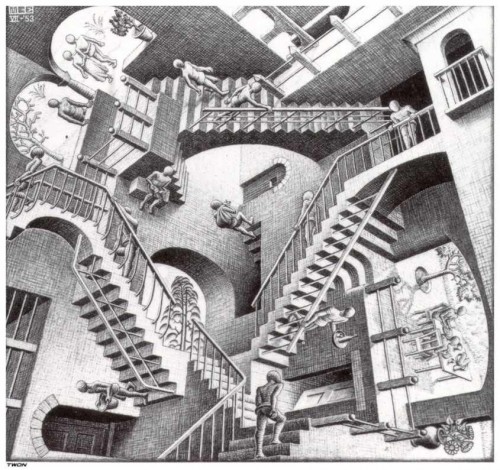
MC Escher Relativity

Much as optical illusions teach us a tremendous amount about how our vision works, auditory illusions provide the same sort of insight as to how our hearing works.

Illusions are a great learning tool because they are both fun and memorable.  Dianna Deutsch has developed some particularly interesting and revealing auditory illusions.

The knowledge of this and other elements of psychoacoustics is essential for audio design, so put on your headphones and enjoy!

Transconductance Amplifiers

transconductance-amplifier

A transconductance amplifier takes an input in voltage and converts it to an output in current.  For a fixed resistive load the result is identical to a typical amplifier (i.e. a voltage amplifier), however for a varying or a reactive load the results are much different.  The relationship between the two is given by Ohm’s law V=I·R.

Given the wildly varying impedance curves of most loudspeakers, why would anybody want to use a transconductance amplifier?  The reason is that research shows a 20-30dB reduction in mid-band distortion is possible with current-driven loudspeakers.  This mode of operation is suitable for MF/HF drivers, but not for LF drivers as the current technology requires the majority of damping about resonance to be provided by the power amplifier.  It is possible this may change in the future if the benefits of current-drive are realized commercially (e.g. with the addition of a shorting ring to control resonance).  Please refer to this paper by Mills and Hawksford.

Distortion mechanisms reduced by current-drive:

• Thermally induced compression
• Nonlinear voice coil inductance
• Hysteresis from metal core
• Eddy current distortion

Another nice feature of transconductance amplifiers is built in overcurrent protection.  Since output current is the controlled variable, shorting the output will not increase the current level.  Also, an open circuit will simply result in amplifier clipping.  The reason for this is that, much as the ideal output impedance of a voltage amplifier is zero, the ideal output impedance of a transconductance amplifier is infinity.

Total Harmonic Distortion

bad-sound

Total Harmonic Distortion (THD) is the standard measurement for the accuracy of audio equipment, particularly audio amplifiers.  Unfortunately, it is a poor metric for audio amplifiers for one simple reason: they are intended to be listened to.  If the amplifier were intended to drive a precision actuator for an industrial process, for example, then perhaps THD would be a good metric, along with bandwidth, slew rate, settling time, etc.

Lower-order harmonic distortion tends to be perceived much more favorably than higher-order harmonic distortion (the ear naturally generates low-order harmonic distortion).  This leads one immediately to at least consider a harmonically weighted distortion metric.  In fact, such a metric was proposed as early as 1937 by the Recording Manufacturers’ Association of America, however such metrics have seen little, if any, practical application.  No doubt this is due in part to the many different choices for harmonic weighting functions, frequency dependent factors, etc. – there are no such choices with THD.

Fairly recently a metric has been proposed that seems to have very good correlation with subjective impression.  This is the “GedLee Metric” by Earl Geddes and Lidia Lee of GedLee LLC.  Here are the first and second parts of the relevant AES papers.  There is a tremendous amount of momentum to overcome for a metric such as this to ever gain traction in the audio industry.  Especially resistant will be any manufacturers that stand to have their specifications suffer by it.  For example, low THD linear amplifiers that have made use of large amounts of global feedback, with little attention given to the linearity of the open-loop transfer function, may look poor in the light of this new metric.

Damping Factor

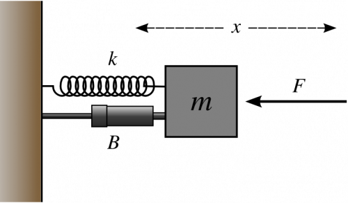
mass-spring-damper

An amplifier’s damping factor is a rating that gives a feel for the amplifiers control over a load.  It is essentially a measure of the output impedance of the amplifier – a value that would be zero for an ideal amplifier (i.e. the ideal amplifier would be load-independent).

Like many measurements of an amplifier’s performance, this one is the victim of misinterpretation and measurement trickery:

First, the exact measurement point has a huge impact on the resulting value.  For example, taking a measurement right at the feedback points of the amplifier tends to give a high damping factor, as this is the actual point the amplifier is attempting to regulate.  Unfortunately, this is rarely where the user connects the load!  The user generally uses the externally accessible speaker connector, so this is the chain that results: the wires/traces from feedback nodes, the contact resistance of the speaker connector, and the external cables that connect to the load.  When this more realistic chain is considered, much more modest damping factors result, however they are much more representative and useful for the user.

Second, the bottom line is that if the amplifier’s effective output impedance is much lower than the minimum impedance of the loudspeaker being driven, there is little to be gained from further increasing the damping factor.  In fact, it may very well be detrimental, given that the typical means of increasing the damping factor is by increasing feedback.  If the feedback is increased excessively it may impact stability and result in lower-amplitude, but more objectionable, harmonics – this will be the topic of a future entry.

Physics Friday – Maxwell’s Equations

Every once in a while it is important to take those dusty tomes down off the top shelf, or out of those boxes behind the furnace in the basement, and remind ourselves exactly what makes all this stuff tick.  Periodically I plan to post a little something about these fundamentals – “Physics Friday”.

This Friday the topic is one that is crucial for electronics: Maxwell’s equations.  There are a few different ways of presenting these equations, the most common one is in integral form.  This is a great form for introducing the topic, but there are only a handful of highly symmetric problems that you can attack with this.  The next most common is in differential form using the del operator with either the dot product or cross product.  This is a very useful form, although it only holds for Cartesian coordinates, which is rarely the coordinate system of choice for E&M problems.  Another differential form uses the “div” and “curl” operators, which are not only coordinate system independent, they are also very intuitive.  The “div” operator is just that – a diverging field (one that tends to move outward to infinity) and the “curl” operator is a curling field (think of the “right hand rule“).

$$div\mathbf{E}=\frac{\rho }{\varepsilon_{0}}$$

A charge density produces a diverging electric field (Gauss’s Law).

$$div\mathbf{B}=0$$

No magnetic monopoles means there is no diverging magnetic field (Gauss’s law for magnetism).

$$curl\mathbf{E}=-\frac{\partial }{\partial t}\mathbf{B}$$

A time-varying magnetic field generates a curling electric field that tends to oppose it (Faraday’s Law).

$$curl\mathbf{B}=\mu _{0}\mathbf{J}+\mu _{0}\varepsilon _{0}\frac{\partial }{\partial t}\mathbf{E}$$

A curling magnetic field is generated by either a current density or a time-varying electric field (Ampere’s Law).

MOSFET Body Diode

Tortoise

By the nature of its construction, a MOSFET has a built-in anti-parallel diode – this is refered to as the intrinsic “body diode”.  It is generally very slow, unless the MOSFET is optimized to have a fast body diode, which unfortunately often has the side effect of increasing the Rds(on) of the MOSFET.

It is usually easier to find fast body diodes in lower voltage MOSFETs than in higher voltage ones, so the body diode tends to be less of an issue with lower power amplifiers (i.e. lower voltage) than with higher power amplifiers (i.e. higher voltage).  IXYS has a notable exception with their “PolarHV™ HiPerFETs” – a series of high voltage MOSFETs with fast intrinsic body diodes.

This article explores the issue of the slow body diode in greater detail and also gives some example means for dealing with it.

MOSFETs versus IGBTs

chuck-norris-bruce-lee

MOSFETs and IGBTs each have their own set of strengths and weaknesses when used in switching audio amplifiers.

MOSFETs only employ “majority carriers“.  For an N-channel MOSFET (the most commonly used due to the much higher mobility of electrons versus holes) the carriers are electrons.  This is a great advantage from a switching speed point of view, as the MOSFET may be turned off very quickly since there are no “minority carriers” to remove from the conducting channel, in order to return it to a non-conducting state.  However, the downside is that no “conductivity modulation” takes place – i.e. the presence of increasing numbers of minority carriers tends to decrease the effective resistance of the conducting channel, much as happens with diodes, or BJTs, or…

IGBTs utilize both majority and minority carriers.  From a switching speed point of view this is a disadvantage because the minority carriers must now be swept from the conducting channel before the IGBT can return to a non-conducting state.  The is the often referred to “current tail” of IGBTs.  Conversely, IGBTs do enjoy the benefits of conductivity modulation, so while MOSFETs are suffering Rds(on)·I² losses, the IGBT suffers only Vce(sat)·I losses.  Even better, the Vce(sat) of the IGBT tends to be roughly constant with temperature (sometimes even decreasing a bit), while the Rds(on) of a MOSFET can increase by up to 2.5 times with increasing temperature.

What does this mean for audio?  Given the high peak-to-average ratio of audio program material, the IGBT is a natural choice, since the losses are roughly proportional to current, instead of proportional to the square of current, as with a MOSFET.  The only problem is the higher switching frequency of switching amplifiers results in extra dissipation due to the minority charge of the IGBT.  This may not be an issue at all in the power supply portion of the switching amplifier, but in the amplifier section it is a little more tricky.  However, with a little ingenuity it is possible to combine the strengths of both devices in the amplifier section as well.  This promises to provide amazingly high efficiency in higher power switching amplifiers.

Cross Pollenization

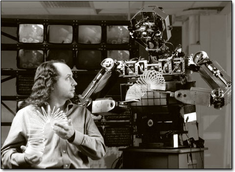
Rodney Brooks Robot

The audio industry is a small one, but luckily there are much larger industries that can be drawn upon both for inspiration and for the components particular to that industry.  For example, many of the MOSFETs and IGBTs available have been driven by the automotive and telecom industries, but they are also well-suited to audio.

Robotics is a good example of a field that can be used for inspiration.  For example, one particularly useful and powerful conecpt is that of “subsumption architecture” developed by Rodney Brooks.  This approach builds a robot up in functional layers: the innermost dealing primarily with functions such as movement and safety, and the outermost dealing primarily with high-level functions, such as path-planning or communication, that are sometimes able to override the lower-level functions.  As applied to audio amplifiers, this concept leads one to build a robust amplifier core that can drive the required load, protect against a short, etc. and then to augment it with layers of higher-level functionality and protection.

One of the earliest lessons I learned in amplifier design was the very fine line between reliability and usability.  If an amplifier is designed to protect aggressively against any possible deviation from the norm, then it is likely a user will trigger a protective measure during legitimate use.  Conversely, if the amplifier is designed solely with the idea that “the show must go on”, then it is likely the user will at some point do something the amplifier really should protect against.  If subsumption architecture is applied, then it allows for the best of both worlds: an amplifier that can protect itself from legitimate abuse via the inner layers, and an amplifier that allows the show to go on via the intelligence located in the outer layers.

Analog versus Digital Class-D Amplifiers

old-and-new

Analog class-D amplifiers at some point convert a small analog signal to a large one.  There may be a DAC up front to allow for digital input, but the bottom line is that the gain is performed in the analog realm.  Digital class-D amplifiers never convert the signal to a small analog signal: the signal remains in the digital realm until the output stage, at which time it becomes a large analog signal.  Also, It is important not to confuse “digital” and “PWM”.  The amplitude of a digital signal is not important as long as it is sufficient to meet the noise margin requirements of the system interpreting it.  The amplitude of a PWM signal is important, because at some point something is going to integrate it – whether the feedback network of the amplifier or the output filter/loudspeaker combination.

One downside to digital class-D amplifiers is that they have no analog feedback.  This means that unless alternate means are used, the amplifier exhibits 0dB PSRR (i.e. any noise in the power supply will find its way to the output).  Some solutions have made use of a well-regulated power supply to reduce this effect, however this is simply “sweeping the dirt under the rug”, by offloading the analog feedback to another part of the circuit.  Other designs use a 1-bit ADC to measure the output signal and provide some means of feedback.  A more elegant solution is to use the DSP that is invariably present to provide feed-forward error correction of the digital signal, based on measured parameters.

Overall, despite the downsides, digital class-D amplifiers are the way the industry is heading, if for no other reason that this one: manufacturability.  Corrections to analog circuitry are difficult during the development process and may be next to impossible once production starts, especially for larger volume products.  However, firmware changes are much easier by comparison and this may be all that is needed to fix problems in a digital amplifier.  When time-to-market is critical, the faster, more efficient solution often wins out.