Archive for the ‘Switching Amplifiers’ Category

How to Design a Class-D Amplifier

Tuesday, December 29th, 2009

 Child With Blocks

This is a very tricky topic.  Any simple article is never going to be enough for a novice to really be able to design a class-D amplifier.  However in this article I attempt to outline the basic requirements and considerations for designing a class-D amplifier.  It isn’t complete, but it’s a good start!

Also, in the article I attempt to draw a parallel between some of the familiar elements of a linear amplifier and the perhaps not-so-familiar elements of a class-D amplifier.  The comparison isn’t perfect, but I hope it will serve as a springboard to those not yet familiar with the intricacies of class-D amplifier design.

Class-D PWM Harmonics

Wednesday, June 24th, 2009

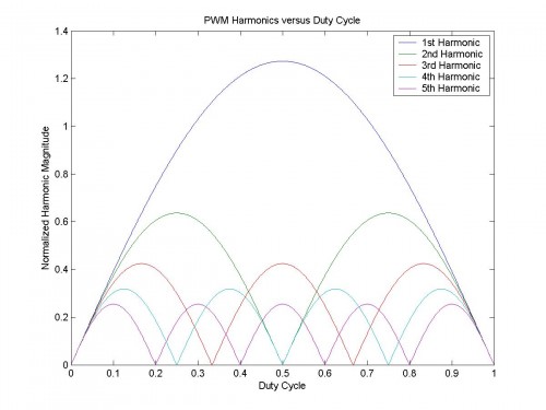
PWM Harmonics versus Duty Cycle

Features to note in this plot of the PWM harmonic content versus the duty cycle:

  • At idle (D=0.5) only odd harmonics are present, as expected from a square wave
  • Away from idle (D<0.5 or D>0.5) even harmonics added, as expected from PWM
  • Magnitudes are equal at duty cycle extremes, as expected from an impulse function


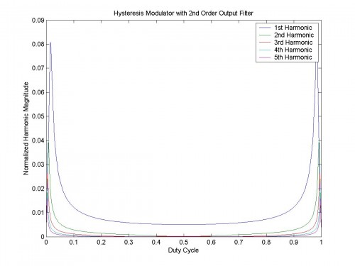
If the class-D amplifier is a hysteresis modulator with a passive 2nd order output filter:

Hysteresis Modulator with 2nd Order Output Filter

Features to note in this new plot of the PWM harmonic content versus the duty cycle:

  • The harmonics increase abruptly as clipping is approached, consistent with observation
  • At idle the output is dominated by the fundamental (i.e. a low level sine wave at $$f_{s}$$)
  • Designs with more stable switching frequency at duty cycle extremes are easier to filter


Switching frequency versus duty cycle relationship for a hysteresis modulator:

$$f_{s}=4D\left ( 1-D \right )f_{0}$$

$$f_{s}$$ is the switching frequency at $$D$$
$$f_{0}$$ is the switching frequency at $$D=0.5$$
$$D$$ is the duty cycle $$0\leq D\leq 1$$

Magnetics Design

Thursday, December 4th, 2008

Horseshoe Magnet

The design of the magnetics for switching supplies and switching amplifiers can be very challenging.  There tends to be an aura of mystery surrounding it, thus making things even worse, but with a few good guidelines and some carefully selected resources it can be reduced to as near a science as engineering ever is…

Guidelines:

• The primary and secondary windings should be as close to each other as possible over their entire extent.  Unfortunately isolation requirements do not usually allow for this.

• If a winding is inserted between a primary and a secondary, then a current will flow in this winding – this can result in significant extra losses.  If it is necessary to do this (e.g. multiple windings in a flyback), then the highest power secondary windings should be placed closest to the primary.

• Making a single winding with multiple layers can result in very high losses.  Refer to “Dowell’s Curves” to see how the number of layers affects the ratio of ac to dc resistance.

• With two adjacent windings, the current will tend to flow on the inside surface of each winding – this is the proximity effect.  This results in even less effective conductor area than would be estimated given the skin effect alone.

• As a general guideline, make core losses as high as practical, relative to copper losses.  This helps to decrease leakage inductance, copper losses, etc.

• Gapped ferrite cores often yield lower core losses than powdered iron cores, however the fringing field due to the discrete gap can result in significantly higher copper losses.

Resources:

• An estimate of the magnetic losses in a design

• A list of magnetics design “myths” from Ridley Engineering

Eddy Current Losses in Transformer Windings by Lloyd Dixon

Magnetics Design for Switching Power Supplies – Section 3 by Lloyd Dixon

• Switching Power Supply Design by Abraham Pressman

• Fundamentals of Power Electronics by Robert Erickson

Switching Supplies for Amplifiers

Wednesday, December 3rd, 2008

power-supply

There are a few switching power supply topologies that are particularly important for audio amplifiers – each with its set of advantages and disadvantages:

Flyback

The flyback tends to be the least expensive of the switching supply types, as it uses only one negative rail-referenced switch.  It also lends itself well to multiple regulated rails, so it makes for a very nice auxiliary supply in an amplifier.  This type of switching supply is generally not used as the main supply for audio amplifiers for these reasons:

• All transferred energy must be stored in the core
• The switching is usually hard switching, which may present issues for audio performance
• Use of a single switch also limits the maximum power

Push-pull

The push-pull makes use of two switches that are both negative rail-referenced.  This type of supply is very useful for car audio amplifier power supplies.  It generally sees little, if any, use in mains-powered audio amplifiers.

Half-bridge

The half-bridge uses two switches as does the push-pull, however one of the switches is not referenced to the negative rail, instead it is “floating”.  This complicates the drive requirements somewhat, however there are significant benefits:

• Resonant switching is easily achieved for higher efficiency and lower system noise
• Resonant transitions are automatically clamped at the rails, so energy due to magnetizing/leakage inductance is recycled
• Maximum use is made of the transformer core and windings

Full-bridge

A full-bridge supply is essentially a combination of two half-bridge supplies with the switch timing adjusted accordingly (i.e. alternating).

There is one interesting variation of the full-bridge supply that allows for both resonant switching and output voltage regulation – this is the phase shifted full-bridge.  It achieves zero-voltage switching (ZVS) which is ideal for MOSFET type switches.  One important detail is that the MOSFETs must have fast intrinsic body diodes or the supply can suffer from reliability issues with light loads.

Power Factor Correction

Power factor correction (PFC) is starting to find its way into amplifier power supplies.  It is not a power supply per se, as it provides no galvanic isolation, rather it is an additional stage that is placed before the main power supply (e.g. half-bridge, full-bridge, etc.)  There are benefits to using a PFC front end:

• Maximized utilization of a given ac service (i.e. unity power factor)
• Universal input (85Vac-265Vac) with a regulated bus voltage
• Higher bus voltage (~400Vdc) for greater bus capacitor energy density

Unfortunately, TANSTAAFL applies and a PFC front end suffers from these downsides:

• Reduced system efficiency (e.g. if the system efficiency is 85% without the PFC and the PFC itself is 85%, then the net efficiency with the PFC is 72%)
• Reduced system reliability (all the power flows through this stage and it is usually a hard-switched topology)
• Possibility of increased EMI and system noise due to high power hard switching

Transconductance Amplifiers

Monday, December 1st, 2008

transconductance-amplifier

A transconductance amplifier takes an input in voltage and converts it to an output in current.  For a fixed resistive load the result is identical to a typical amplifier (i.e. a voltage amplifier), however for a varying or a reactive load the results are much different.  The relationship between the two is given by Ohm’s law V=I·R.

Given the wildly varying impedance curves of most loudspeakers, why would anybody want to use a transconductance amplifier?  The reason is that research shows a 20-30dB reduction in mid-band distortion is possible with current-driven loudspeakers.  This mode of operation is suitable for MF/HF drivers, but not for LF drivers as the current technology requires the majority of damping about resonance to be provided by the power amplifier.  It is possible this may change in the future if the benefits of current-drive are realized commercially (e.g. with the addition of a shorting ring to control resonance).  Please refer to this paper by Mills and Hawksford.

Distortion mechanisms reduced by current-drive:

• Thermally induced compression
• Nonlinear voice coil inductance
• Hysteresis from metal core
• Eddy current distortion

Another nice feature of transconductance amplifiers is built in overcurrent protection.  Since output current is the controlled variable, shorting the output will not increase the current level.  Also, an open circuit will simply result in amplifier clipping.  The reason for this is that, much as the ideal output impedance of a voltage amplifier is zero, the ideal output impedance of a transconductance amplifier is infinity.

MOSFET Body Diode

Thursday, November 27th, 2008

Tortoise

By the nature of its construction, a MOSFET has a built-in anti-parallel diode – this is refered to as the intrinsic “body diode”.  It is generally very slow, unless the MOSFET is optimized to have a fast body diode, which unfortunately often has the side effect of increasing the Rds(on) of the MOSFET.

It is usually easier to find fast body diodes in lower voltage MOSFETs than in higher voltage ones, so the body diode tends to be less of an issue with lower power amplifiers (i.e. lower voltage) than with higher power amplifiers (i.e. higher voltage).  IXYS has a notable exception with their “PolarHV™ HiPerFETs” – a series of high voltage MOSFETs with fast intrinsic body diodes.

This article explores the issue of the slow body diode in greater detail and also gives some example means for dealing with it.

MOSFETs versus IGBTs

Wednesday, November 26th, 2008

chuck-norris-bruce-lee

MOSFETs and IGBTs each have their own set of strengths and weaknesses when used in switching audio amplifiers.

MOSFETs only employ “majority carriers“.  For an N-channel MOSFET (the most commonly used due to the much higher mobility of electrons versus holes) the carriers are electrons.  This is a great advantage from a switching speed point of view, as the MOSFET may be turned off very quickly since there are no “minority carriers” to remove from the conducting channel, in order to return it to a non-conducting state.  However, the downside is that no “conductivity modulation” takes place – i.e. the presence of increasing numbers of minority carriers tends to decrease the effective resistance of the conducting channel, much as happens with diodes, or BJTs, or…

IGBTs utilize both majority and minority carriers.  From a switching speed point of view this is a disadvantage because the minority carriers must now be swept from the conducting channel before the IGBT can return to a non-conducting state.  The is the often referred to “current tail” of IGBTs.  Conversely, IGBTs do enjoy the benefits of conductivity modulation, so while MOSFETs are suffering Rds(on)·I² losses, the IGBT suffers only Vce(sat)·I losses.  Even better, the Vce(sat) of the IGBT tends to be roughly constant with temperature (sometimes even decreasing a bit), while the Rds(on) of a MOSFET can increase by up to 2.5 times with increasing temperature.

What does this mean for audio?  Given the high peak-to-average ratio of audio program material, the IGBT is a natural choice, since the losses are roughly proportional to current, instead of proportional to the square of current, as with a MOSFET.  The only problem is the higher switching frequency of switching amplifiers results in extra dissipation due to the minority charge of the IGBT.  This may not be an issue at all in the power supply portion of the switching amplifier, but in the amplifier section it is a little more tricky.  However, with a little ingenuity it is possible to combine the strengths of both devices in the amplifier section as well.  This promises to provide amazingly high efficiency in higher power switching amplifiers.

Analog versus Digital Class-D Amplifiers

Monday, November 24th, 2008

old-and-new

Analog class-D amplifiers at some point convert a small analog signal to a large one.  There may be a DAC up front to allow for digital input, but the bottom line is that the gain is performed in the analog realm.  Digital class-D amplifiers never convert the signal to a small analog signal: the signal remains in the digital realm until the output stage, at which time it becomes a large analog signal.  Also, It is important not to confuse “digital” and “PWM”.  The amplitude of a digital signal is not important as long as it is sufficient to meet the noise margin requirements of the system interpreting it.  The amplitude of a PWM signal is important, because at some point something is going to integrate it – whether the feedback network of the amplifier or the output filter/loudspeaker combination.

One downside to digital class-D amplifiers is that they have no analog feedback.  This means that unless alternate means are used, the amplifier exhibits 0dB PSRR (i.e. any noise in the power supply will find its way to the output).  Some solutions have made use of a well-regulated power supply to reduce this effect, however this is simply “sweeping the dirt under the rug”, by offloading the analog feedback to another part of the circuit.  Other designs use a 1-bit ADC to measure the output signal and provide some means of feedback.  A more elegant solution is to use the DSP that is invariably present to provide feed-forward error correction of the digital signal, based on measured parameters.

Overall, despite the downsides, digital class-D amplifiers are the way the industry is heading, if for no other reason that this one: manufacturability.  Corrections to analog circuitry are difficult during the development process and may be next to impossible once production starts, especially for larger volume products.  However, firmware changes are much easier by comparison and this may be all that is needed to fix problems in a digital amplifier.  When time-to-market is critical, the faster, more efficient solution often wins out.

Class-D Efficiency

Sunday, November 23rd, 2008

Ice Cube Fire

The maximum theoretical efficiency for a linear amplifier is about 78.5%.  This assumes zero idle losses and static supply rails (i.e. not a class-G or class-H amplifier).  The maximum theoretical efficiency of a switching amplifier is 100%.  This assumes zero idle losses and “perfect” switching devices.  Of course you can never really achieve 100% efficiency – the second law of thermodynamics forbids this – but you can achieve 90%, 99%, 99.9% and 99.99% as the technology improves to allow for it.

The determination of efficiency is a fairly straightforward measurement for a given product.  Unfortunately, marketing sometimes gets a hold of it and the following scenario occurs:

Worldly marketing type:  “Hey Bob, sweet amp.”

Innocent engineering type:  “Gee Fred, ya think so?  Thanks!”

Worldly marketing type:  “Yah, but we could really improve our position against XYZ if the efficiency were higher than 75%…”

Innocent engineering type:  “But I’m giving the end-to-end efficiency and XYZ is claiming an efficiency of 99.5% by only including the losses in the power cord!”

Worldly marketing type:  “Uh-huh.”

Innocent engineering type:  [Exasperated] “Okay, fine.  I’ll work on it after I take my Honda in for an oil change at lunch.  How’s the Bimmer working out for ya?”

Worldly marketing type:  “Fine, just fine.”

The bit about the car types was inspired by Guy Kawasaki.

Class-D Supply Pumping

Tuesday, November 18th, 2008

Oil Pump

Much has been made over the phenomenon of “supply pumping” in single-ended class-D amplifiers (i.e. not a full-bridge output). Maybe it is an issue, maybe it isn’t, but it is very difficult to answer that question unless we have some numbers to work with! This is not the sort of thing you can simply listen to on your reference system and say, “Yes, now I’m sure of it: roughly 15V peak at 20Hz.” Well, maybe you can, but I certainly can’t.

This article derives the magnitude of the supply pumping in terms of known parameters of the amplifier: rail voltage, bus capacitance, load impedance and frequency. It shows that the only variable the designer really has control over for the reduction of supply pumping is bus capacitance, at least without resorting to more advanced methods, but adding more capacitance is the simplest and gives the best results by far.