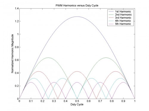
Features to note in this plot of the PWM harmonic content versus the duty cycle:
- At idle (D=0.5) only odd harmonics are present, as expected from a square wave
- Away from idle (D<0.5 or D>0.5) even harmonics added, as expected from PWM
- Magnitudes are equal at duty cycle extremes, as expected from an impulse function
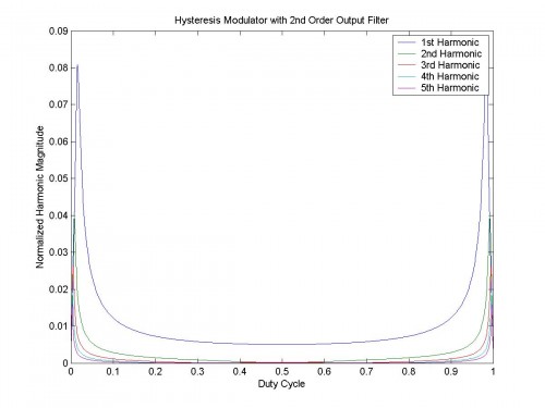
If the class-D amplifier is a hysteresis modulator with a passive 2nd order output filter:
Features to note in this new plot of the PWM harmonic content versus the duty cycle:
- The harmonics increase abruptly as clipping is approached, consistent with observation
- At idle the output is dominated by the fundamental (i.e. a low level sine wave at $$f_{s}$$)
- Designs with more stable switching frequency at duty cycle extremes are easier to filter
Switching frequency versus duty cycle relationship for a hysteresis modulator:
$$f_{s}=4D\left ( 1-D \right )f_{0}$$
$$f_{s}$$ is the switching frequency at $$D$$
$$f_{0}$$ is the switching frequency at $$D=0.5$$
$$D$$ is the duty cycle $$0\leq D\leq 1$$

